Planning an FTTx Fibre Rollout in Egypt
Fibre to the home, building or premises is the backbone of modern broadband. A successful FTTx rollout depends less on the fibre itself and more on survey quality, sound design, disciplined civil works and rigorous testing. This guide walks through each stage and the checks that protect the network for decades.
Why FTTx planning matters in Egypt
Fibre networks are expanding across Egypt, from new cities and compounds to rural villages connected under the national Haya Karima (Decent Life) programme. Real estate developers, operators, industrial zones and campuses all need fibre that is built right the first time.
Fibre itself is a long-life asset, but mistakes are costly. A poorly routed duct, a bad splice or a missing record can mean digging up a finished road. Good planning keeps the cost per home passed under control and makes later expansion simple.
It also helps to be clear about who the network serves. An operator building FTTH for retail broadband, a developer wiring a new compound, and an industrial zone connecting factories all have different priorities for capacity, resilience and time to revenue. Define the business objective, the target number of homes or premises passed and the expected take-up rate before any design work starts, because these numbers drive every later decision.
Stage 1: Survey and data collection
Every reliable design starts with field data. A survey should capture:
- Demand points: buildings, units and expected subscribers, now and at full build-out.
- Routes: roads, existing ducts, poles, crossings of railways, canals and highways.
- Permits: the authorities and owners whose approvals are needed for each route.
- Constraints: utilities, soil type, water table and areas where trenching is restricted.
- Sites for the central office or OLT, cabinets and splitter locations.
Capture everything in GIS from day one. Geo-referenced survey data becomes the foundation for design, permitting, construction tracking and the final as-built records.
Permitting deserves special attention. Routes often cross land controlled by several bodies, such as local authorities, road agencies, irrigation authorities and private owners, and each has its own process and timeline. Start permit applications as soon as the preliminary route is known, and keep alternative routes ready for sections where approval may be slow.
Stage 2: Network design (GPON, XGS-PON and architecture)
Most FTTx networks use passive optical networking. GPON is defined in ITU-T G.984, and XGS-PON in ITU-T G.9807.1, which offers symmetric 10 Gbit/s and can coexist on the same fibre with GPON. Designing for XGS-PON readiness now protects the investment.
Key design decisions include:
- Split architecture: centralised splitting or cascaded (distributed) splitting, with typical ratios such as 1:32 or 1:64.
- Optical power budget: sum the losses of fibre, splices, connectors and splitters, and keep a safety margin within the optics class you deploy.
- Fibre types: ITU-T G.652.D single-mode for feeder and distribution, and bend-insensitive G.657.A1 or A2 for drops and in-building runs.
- Spare capacity: extra fibres and duct space for growth, business customers and mobile backhaul.
- Labelling and records: a consistent naming scheme for every cable, closure, splitter and port.
Design for operations as well as construction: group fibres logically, leave slack at key points and keep splitter locations accessible for technicians.
The output is a set of route drawings, splicing schematics, a bill of quantities and a power budget for every path.
Review the design against the survey before construction. Desk designs that ignore field realities, such as blocked ducts, missing poles or unexpected utilities, cause most of the change orders that inflate FTTx budgets.
Stage 3: Civil works and cable installation
Civil works are usually the largest share of cost and time. Choose the method to suit each segment:
- Open trenching for new developments and soft ground.
- Micro-trenching for urban roads where disruption must be minimal.
- Horizontal directional drilling for road, canal and rail crossings.
- Aerial cable on existing poles where permitted.
- In-building risers and pathways for multi-dwelling units.
Quality controls matter at every step: correct trench depth and warning tape, duct integrity tests before blowing cable, sealed duct ends, handholes and manholes at agreed spacing, and reinstatement to the authority's standard. Record each section with photos and GPS points.
Plan civil works in clusters so that each area can be completed, tested and handed over before crews move on. This gives early revenue from finished areas, limits the time roads stay open, and makes quality problems visible while the team is still on site. Daily progress reports against the GIS plan help project managers spot delays early.
Stage 4: Splicing and termination
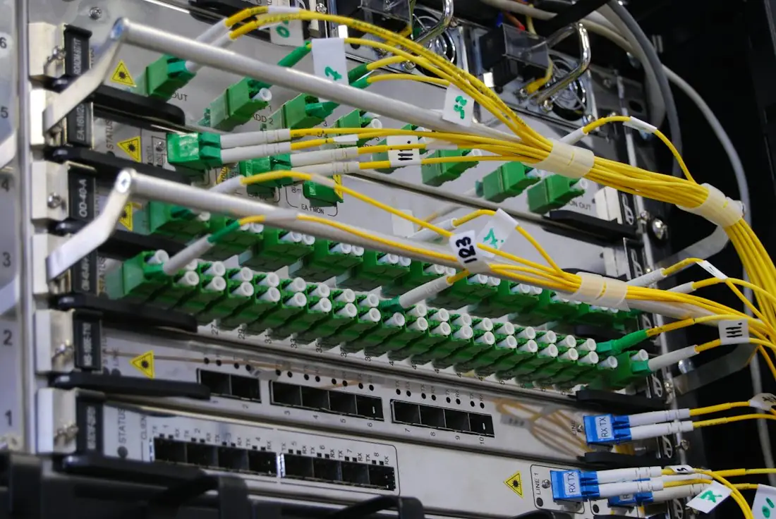
Fusion splicing joins fibres with very low loss. Good practice includes clean preparation, calibrated splicers, protected splices in organised trays and closures sealed for the environment.
Project specifications usually set limits for average splice loss and connector loss. Agree these numbers in the contract, together with how they will be measured. Splitters, ODFs and customer termination points should follow the labelling scheme from the design stage, so every port can be traced from the OLT to the home.
Closures should be placed where they can be reached for maintenance without excavation or traffic disruption, with slack cable stored neatly for future re-entry. Record each closure's location, fibre allocation and splice details. When a fault occurs years later, this information decides whether repair takes an hour or a day.
Stage 5: OTDR testing and acceptance
Testing proves the network was built as designed. Two complementary tests are standard:
- Optical loss testing with a light source and power meter, following methods such as IEC 61280-4-2 for single-mode, to confirm end-to-end loss fits the power budget.
- OTDR testing to locate and measure each splice, connector and bend. Testing at 1310 nm and 1550 nm, and at 1625 nm where macro-bends must be detected, is common. Bi-directional testing gives accurate splice values.
An acceptance package should include test results for every fibre, as-built GIS records, splicing diagrams, photos, permits closed out and a punch list. Only accept segments once the punch list is cleared. These records become the maintenance team's most valuable tool.
How Novatelx delivers it
Novatelx manages FTTx and backbone projects through ten gated stages: survey, design, permitting support, supply, civil works with our partner Proxima, cable installation, splicing, testing and acceptance, followed by operation and maintenance.
Each gate has defined deliverables, so owners see progress and quality before the next stage starts. See our fibre backbone and FTTx rollout package and, for ongoing support, our field maintenance and technical outsourcing package.
Frequently asked questions
What is the difference between FTTH, FTTB and FTTx?
FTTx is the umbrella term. FTTH brings fibre all the way into each home. FTTB brings fibre to the building, with the final link over existing copper or in-building cabling. FTTC stops at a street cabinet. FTTH gives the best performance and future-proofing, while FTTB can be faster to deploy in existing buildings.
What split ratio should a GPON network use?
Common ratios are 1:32 and 1:64, either in one stage or cascaded across two. The right choice depends on subscriber density, the optical power budget and the bandwidth per user you plan to offer. Higher split ratios save fibre but reduce the loss margin and share capacity among more users.
Why is OTDR testing needed if the power meter test passes?
A power meter test confirms total loss but not where it occurs. An OTDR trace shows each splice, connector and bend along the fibre, so it can reveal a poor splice hidden within an acceptable total. It also provides a baseline trace that speeds up fault-finding later.
What fibre type is used for FTTH drops?
Drop cables and in-building runs normally use bend-insensitive single-mode fibre to ITU-T G.657.A1 or A2, which tolerates tight bends around corners and inside walls. Feeder and distribution cables usually use standard G.652.D fibre. Both are compatible and can be spliced together.
What should an FTTx acceptance package include?
It should include OTDR and loss test results for every fibre, as-built routes in GIS, splicing schematics, labelling records, photos of key installations, closed-out permits and a cleared punch list. These documents prove quality at handover and are essential for future maintenance and expansion.
Discuss your project with our engineers
Send the sites, the timeline and how success will be measured, and we will come back with a clear plan.
Talk to an engineer Structured Cabling & Data Centre Standards Guide
 Managed SOC vs In-House SOC: How to Decide
 Bank & Fintech Cybersecurity Checklist for Egypt